Controlling home lamp using internet
As I was browsing through Amazon, searching for things to buy which I do not need I came across this lamp which could be controlled through the internet. It was quite expensive so I thought of building my own. The way the lamp worked was that, it came with a QR code on top of it, and when scanned with the phone (which is connected with a wi-fi), the lamp gets connected and if both the devices are connected to the same wifi, we could control the lamp. That however is an issue since I wish to control my lamp from anywhere and not just from my room.
I searched for options to do that for my existing table lamp, and I came across a smart plug which could literally make any of the appliances “smart”. This would have costed around ₹2000, and I decided to create my own “smart” plug.
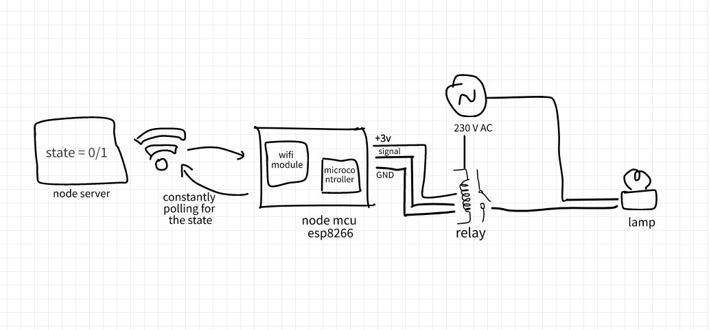
The idea was simple, I just needed a web server where I would store the state of the switch, something that would poll my server all the time and would turn the lamp on/off according to the state. I thought of using Arduino and some wifi module, but I came across ESP8266-NodeMCU, which is again a microcontroller but it comes fitted with embedded WiFi capabilities, with the lowest costs. These chips are developed in China, and you can get one for as low as ₹200. It has an operating voltage of 3.0-3.6V and the package size was pretty small, so it could be fitted in my existing switch boards. This comes with 17 GPIO pins, and even one was enough for my POC. The GPIO pins give out the signal which can be low or high depending on the code. If I could just poll the web server, and get the state, and send out the signal through the GPIO pin, the lamp could be turned on or off. Now ofcourse, the GPIO pin would give a high signal of 3V DC, and the appliances run on 230 V AC. I used a relay for this purpose. A Relay is basically an electromechanical device that can be used to make or break an electrical connection. It consists of a flexible moving mechanical part which can be controlled electronically through an electromagnet, basically, a relay is just like a mechanical switch but you can control it with an electronic signal instead of manually turning it on or off. So it served the purpose. I sketched out the architecture, before actually starting with the coding part of what I was about to built and it looked something like this.
Now, that everything was in place, I ordered a nodeMCU ESP8266, a relay, some jumper wires, and that is it.
I used the arduino IDE itself for programming the nodeMCU. Luckily, tons of libraries exist for running nodeMCU using the arduino IDE. Parallely I created an API with two endpoints. The GET request would be used by the microcontroller to get the state of the switch, and the PATCH request, will toggle the state -> state = 1 - state. I had connected a free MongoDB database with just one entry, and hosted the API on a free (making it low cost :P) server by Heroku.
I also gave a neat UI which would send a patch reuest for toggling the state, and hosted it on github pages. Here is the UI. Tapping on the button would turn the lamp in my room on/off.
Below is the code for the setup method.
  pinMode(D7, OUTPUT);
  delay(1000);
  Serial.begin(9600);
  WiFi.mode(WIFI_OFF);        //Prevents reconnection issue (taking too long to connect)
  delay(1000);
  WiFi.mode(WIFI_STA);
  WiFi.begin(ssid, password);

  Serial.print("Connecting");
  // Waiting for connection
  while (WiFi.status() != WL_CONNECTED) {
    delay(500);
    Serial.print(".");
  }

  //If connection successful show IP address in serial monitor
  Serial.println("");
  Serial.print("Connected to ");
  Serial.println(ssid);
  Serial.print("IP address: ");
  Serial.println(WiFi.localIP());  //IP address assigned to your ESP
Now that the wifi is connected and the pins are in place, coming to the loop method.
The below code sends a GET request to the server and stores the output in the line variable.
httpsClient.print(String("GET ") + Link + " HTTP/1.1\r\n" +
               "Host: " + host + "\r\n" +
               "Connection: close\r\n\r\n");

  Serial.println("request sent");

  while (httpsClient.connected()) {
    String line = httpsClient.readStringUntil('\n');
    if (line == "\r") {
      Serial.println("headers received");
      break;
    }
  }
There was no need to actually use a json parser since the server would just return a single line with the status. Finally, on checking the output received, a low signal was sent to the Relay to turn on the lamp and a high signal to turn off the lamp.
String line;
  while(httpsClient.available()){
    line = httpsClient.readStringUntil('\n');
    if(line[10] == '1'){
      digitalWrite(D7, LOW);
    }else{
      digitalWrite(D7, HIGH);
    }
    Serial.println(line[10]);
  }
You can view the code for the server here
So I was able to complete this home auto project within a fraction of what I would get online.
Thanks for reading!
Powered by Jekyll